A slip on flange is chosen every day because it’s fast to align, straightforward to fabricate, and usually more economical than heavier flange options. In real plants, though, the slip-on joint is also one of the easiest places to “lose discipline,” because it looks simple. That’s why the most common failures are rarely mysterious. They’re usually the predictable result of small workmanship gaps that add up, such as imperfect fit-up, fillet weld defects, weld distortion that harms flange flatness, and bolting practices that don’t maintain gasket compression after temperature and pressure cycles.
This guide focuses on what actually prevents failures in the field: the details of fit-up, welding technique, distortion control, inspection strategy, and flange assembly. It also ties those practices back to what reputable engineering literature repeatedly shows about leakage: gasketed flange joints tend to leak when gasket contact stress drops over time, often because of bolt load relaxation and permanent deformation effects at the flange–gasket interface.
What a slip-on flange is, and why its welding details matter
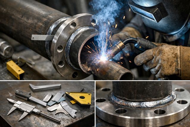
A slip on flange slides over the outside diameter of a pipe and is attached using fillet welds rather than a full-penetration butt weld. That geometry makes alignment easier, but it also concentrates stress at the weld toes and makes joint integrity more sensitive to weld size, weld profile, and distortion. It’s also common for fabricators to weld both the inside and outside, which can improve strength but can introduce a trapped annular space that deserves attention for certain services.
ASME B31.3 includes a precautionary note in Appendix F discussing slip-on flanges and specifically calls out that venting the space between welds in double-welded slip-ons should be considered for services that require leak testing of the inner fillet weld, or when the fluid can diffuse into the enclosed space and lead to possible failure.
That single point explains why slip-on flange reliability is not only about “making a weld.” It’s about understanding what the joint becomes after welding, how it behaves under thermal cycling and vibration, and how sealing performance depends on preserving contact stress at the gasket.
The most common slip-on flange failure modes in service
Leakage that seems like a gasket problem, but is really a stress problem
A frequent pattern is that the flange passes a hydrotest, runs fine during commissioning, and then develops a weep after thermal cycles or a few startups. Many researchers and reviews point to the same mechanism: leakage often occurs because contact stress at the flange–gasket interface reduces over time due to bolt load relaxation and permanent deformation effects, rather than because the gasket was “bad” on day one.
This matters for slip-on flanges because welding heat and distortion can reduce face flatness, which makes gasket compression less uniform. Even if the bolts are tightened to the same torque, the gasket may not see the same compression everywhere.
Fillet weld defects that become cracks under cycling
Slip-on flanges depend on fillet welds, so their long-term reliability is tied to throat size, fusion quality, and weld toe shape. If the weld is undersized, has lack of fusion at the interface, or leaves a sharp toe transition, the joint becomes more vulnerable to vibration and cyclic stresses. In rotating equipment lines, poorly blended toes can act as crack starters. In thermal cycling services, differential expansion can repeatedly load the weld area.
Crevice and trapped-media corrosion in double-welded configurations
When inside and outside fillet welds are both applied, the region between them can trap media. ASME B31.3’s Appendix F language is widely discussed by practitioners because it highlights the risk: if fluid can diffuse into the enclosed space, it can contribute to damage or failure, so venting should be considered in relevant services.
It’s also common for some company specifications to explicitly require a vent hole for slip-on flanges, illustrating how organizations turn that “consider venting” concept into a build requirement when service risk justifies it.
Distortion and face damage that quietly sabotage sealing
Another common failure path is distortion of the flange ring or damage to the flange facing during welding, grinding, or handling. Once the face is warped or the serrations are damaged, the gasket won’t compress uniformly. At that point, the joint may only seal temporarily, or it may require excessive bolt load that accelerates gasket creep and bolt relaxation.
Slip-on flange welding best practices that prevent failures
Slip-on flange fit-up and alignment control
Fit-up is where most good welds begin, and most bad welds become inevitable. The pipe should be square to the flange face, and the flange should sit naturally without being forced into position by bolting. When a spool is “pulled into alignment” by tightening the flange bolts, that creates a hidden bending load. That bending load can reduce gasket stress in part of the circumference, and when combined with relaxation after startup, it can create the conditions for a leak consistent with the contact-stress reduction mechanism reported in bolted-flange studies.
In practice, the biggest improvement is simply refusing to accept forced alignment as “close enough.” If alignment is off, correct the spool or support condition rather than letting the bolted joint become a structural correction tool.
Surface preparation that supports fusion and reduces defects
Because the weld is fillet-based, the interface cleanliness between pipe OD and flange bore matters. Mill scale, paint, oil, or moisture can contribute to lack of fusion and porosity at exactly the interface you most need to be sound. Cleaning to bright metal in the weld zone and keeping the flange face protected from spatter and grinding damage are small steps that prevent the typical defects inspectors later struggle to interpret.
Fillet weld sizing: use code-driven requirements, not habit
Undersized fillet welds are one of the most common and preventable causes of slip-on flange issues. In some contexts, people look to component standards or industry summaries for “typical practice,” such as the frequent statement that internal and external fillet welds are applied on slip-on flanges.
The higher-integrity approach is to anchor weld sizing and acceptance to the governing construction code and project specification, because those documents control what is acceptable for that service and risk category. Treat any “rule of thumb” as a starting conversation, not a requirement. If your project is built under ASME B31.3, B31.3 governs how you qualify procedures, qualify welders, and judge acceptability. If your project is under a pressure vessel code or other jurisdiction, the applicable code and design details change.
Inside fillet weld versus outside fillet weld, and the venting decision
Many shops prefer welding both sides because it can improve strength and seal integrity, but double welding also raises the venting question. ASME B31.3 Appendix F explicitly recommends considering venting in double-welded slip-ons for services requiring leak testing of the inner fillet weld, or where diffusion into the enclosed space could cause failure.
If you decide venting is appropriate, the “best practice” is not only drilling a hole. It is also documenting why it is required, verifying its placement does not compromise code or client requirements, and ensuring the hole does not become a corrosion or leak path later. Some organizations encode this in their welding specifications with defined vent-hole details, showing how it can be implemented in a controlled, repeatable way.
Distortion control: the most overlooked leak-prevention step
Slip-on flange leakage often gets blamed on the gasket, but flange face distortion is frequently the hidden culprit. Controlling distortion starts with tack strategy and welding sequence. Balanced tacks around the circumference reduce the chance the flange pulls to one side. A controlled sequence that distributes heat rather than concentrating it in one run helps keep the flange flat. Sensible control of interpass temperature matters because overheating can soak the flange ring and increase warpage risk.
If your organization sees a recurring pattern of “it seals cold, leaks hot,” treat flange flatness checks and face condition verification as part of the welding quality system, not an afterthought.
Weld profile and toe blending for cyclic services
If the line is subject to vibration or frequent thermal cycling, weld toe profile matters more than people expect. Sharp transitions concentrate stress; smoother transitions reduce stress concentration and can improve fatigue behavior. You can’t grind or reshape indiscriminately without respecting acceptance requirements and minimum weld size, but within allowable practice, attention to toe profile is one of the simplest reliability upgrades.
Inspection and testing practices that catch problems early
Visual inspection remains the highest-value step for slip-on fillet welds because common defects often reveal themselves in profile and surface appearance. Look for undercut at the flange side, inadequate throat, visible porosity clusters, overlap, and any cracking at toes.
For higher-risk services, adding surface examination methods can be valuable because cracks commonly initiate at weld toes. The governing code and project requirements should define what is mandatory, but from a reliability standpoint, the key is aligning inspection intensity with service severity.
Testing strategy also deserves thought. A hydrotest is useful, but it does not always predict how a joint behaves after temperature cycles. Many leakage mechanisms are time- and temperature-dependent, consistent with research and technical discussions of bolt relaxation and gasket behavior.
Bolting, gasket compression, and why welding alone won’t save the joint
Even a flawless weld cannot compensate for poor flange assembly practices. The bolted flange joint seals because bolts create gasket compression, and many reputable sources emphasize that sealing capability is directly related to the bolt-up strategy.
ASME PCC-1 exists specifically to provide guidelines for pressure boundary bolted flange joint assembly, and ASME itself summarizes its scope as applying to pressure-boundary flanged joints with ring-type gaskets located within the bolt circle.
The practical takeaway is that consistency beats hero torque. If torque is used, friction variability makes torque a noisy proxy for bolt tension, so calibration, lubrication control, and a disciplined tightening sequence matter. Where feasible, tensioning methods can reduce variability. For some gasket types and temperature regimes, relaxation occurs after assembly, and reputable gasket manufacturers publish technical guidance emphasizing that unmanaged relaxation can compromise sealing performance and that retorque strategy should be considered where appropriate and safe.
A realistic failure scenario, explained without blaming the gasket
Consider a slip-on flange on a line that sees daily temperature swings. The job is welded and visually accepted. A hydrotest passes. Two weeks later, the joint weeps at one quadrant.
A common cause chain is that welding heat slightly distorts the flange face, gasket compression becomes non-uniform, and then bolt load relaxes after several heat cycles. Research literature on flange joint behavior consistently emphasizes that leakage commonly follows reduction of contact stress at the flange–gasket interface over time, driven by bolt relaxation and permanent deformation effects.
In that situation, simply tightening harder may temporarily stop the leak, but it doesn’t address the system problem. The durable fix is improved distortion control during welding, verification of face condition, and PCC-1-aligned assembly discipline so the gasket sees the compression it needs after the joint settles.
FAQ: slip-on flange welding questions
What is a slip on flange used for?
A slip on flange is used to connect piping where ease of alignment and faster installation are priorities. The flange slides over the pipe, the joint is typically secured by fillet welds, and sealing is achieved with a bolted gasketed connection.
Do slip-on flanges need welding on both sides?
It depends on the governing code, service severity, and project specification. Some practices use inside and outside fillet welds, but if double welding is used, ASME B31.3 Appendix F advises considering venting the enclosed space for certain services, including cases involving leak testing of the inner weld or fluids that can diffuse into the trapped area and contribute to failure.
Why do slip-on flange joints leak after startup even when they passed hydrotest?
A common reason is that gasket contact stress drops after assembly due to bolt load relaxation, gasket deformation, and thermal effects. Engineering literature reviews describe leakage as frequently tied to reductions in contact stress at the flange–gasket interface over time, not just “a bad gasket.”
Does ASME PCC-1 apply to slip-on flange joints?
ASME PCC-1 provides guidance for pressure boundary bolted flange joint assembly practices, and its scope includes pressure-boundary flanged joints with ring-type gaskets located within the bolt circle. It is commonly used to standardize alignment, tightening practice, and assembly discipline in ways that reduce leakage risk.
Conclusion: how to keep a slip on flange from failing in the real world
Preventing slip on flange failures is not one magic step, and it’s not solved by changing gasket brands every time a joint weeps. Reliability comes from controlling the whole chain: precise fit-up without forced alignment, clean surfaces that support fusion, code-driven fillet weld sizing and sound weld profile, distortion control that preserves flange face flatness, inspection methods matched to service risk, and disciplined flange assembly that maintains gasket compression after the joint relaxes in operation. The credibility of that approach is reinforced by engineering literature that repeatedly connects leakage to loss of gasket contact stress over time, often driven by bolt load relaxation and deformation effects.


Leave a comment